Designing the GhostBridge Rev 12 Enclosure
What twelve OpenSCAD revisions changed, with dimensions and details verified from the final Rev 12 source.
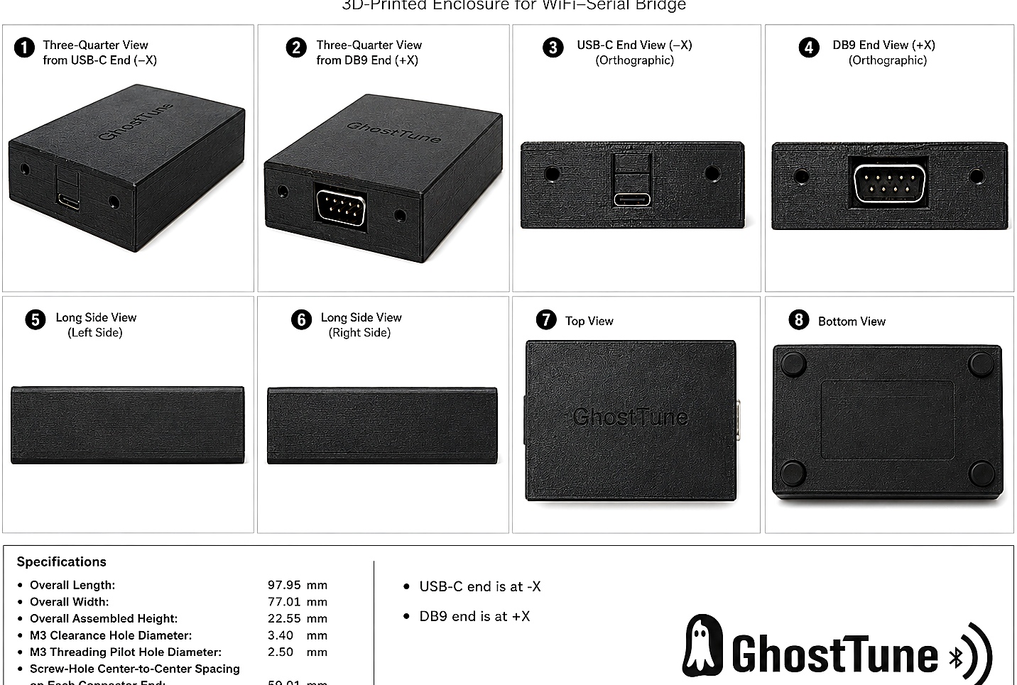
Verified Rev 12 dimensions
| Feature | Rev 12 value |
|---|---|
| Outer enclosure | 97.95 × 77.01 × 22.55 mm |
| Internal cavity | 91.95 × 71.01 mm |
| Main wall | 3.0 mm |
| Lid plate | 2.0 mm |
| Locating lip | 1.0 mm thick × 2.0 mm high |
| Screw-support rails | 5.0 mm thick × exactly 10.0 mm long |
| USB-C opening body allowance | 8.95 × 6.36 mm body plus 0.30 mm clearance per side and vertically |
| DB9 opening body allowance | 30.85 × 12.50 mm body plus 0.30 mm clearance per side and vertically |
| USB-C local wall | 1.0 mm at the connector zone, reinforced to a 1.80 mm root |
| DB9 lid-closure overlap | 1.50 mm |
| Deboss | 0.35 mm depth with 1.20 mm line width |
Why OpenSCAD
The enclosure is defined parametrically. PCB size, cavity size, wall thickness, connector openings, screw locations, clearances, lip geometry, rails, ribs, and branding are calculated from named values rather than redrawn manually.
What Rev 12 corrected
Rev 12 retained the reinforced DB9 closure introduced in Rev 10 and the tapered USB-C closure introduced in Rev 11. It shortened and centered all four screw-support rails to exactly 10.00 mm around the screw axes.
The rails now stop inside the base cavity wall while overlapping the locating lip by 0.30 mm. The two anti-flex ribs were also shortened so they overlap the lip by 0.30 mm without piercing its outer face.
Connector clearance
The USB-C connector projects only about 1 mm beyond the PCB edge. A full 3 mm wall at that location could prevent a cable shell from seating, so the wall is recessed to 1 mm in the connector zone and reinforced inward with a tapered root.
The DB9 connector occupies most of the opposite short wall. Its lid closure overlaps the lid plate by 1.50 mm while preserving the outside endpoint and connector-top clearance.
Lid, screws, and ribs
The lid uses a 1 mm perimeter locating lip that drops 2 mm into the base cavity. Four side screws pass through 3.4 mm clearance holes in the base and thread into 2.5 mm pilot holes in the lid rails. Two 1.5 mm ribs reduce center flex without crossing the outer lip face.
Source publication
The final source is maintained as the dimensional authority for the enclosure. Public source publication is planned after the production validation cycle; until then, published measurements and renders should be checked against that file rather than recreated from visual estimates.